How to Find the Correct Emissivity Setting for an Infrared Temperature Sensor
For accurate results when using an infrared temperature sensor (pyrometer), the emissivity setting must be correct. Here are some methods to help you find the right setting to use.
What is Emissivity?
Emissivity is a measure of how effectively a surface emits infrared energy. For most materials, emissivity is the opposite of reflectivity. A high emissivity makes a surface easy to measure using an infrared thermometer; a low emissivity is more of a challenge.
Emissivity is usually about 0.95 for most non-reflective non-metals. This is the default emissivity setting of all Calex sensors.
What is the Emissivity Setting of the Sensor?
The emissivity setting tells the sensor how emissive the surface is, and improves the accuracy of the measurement when it is set correctly.
Some sensors, such as the PyroCouple, have a fixed emissivity setting of 0.95, with no adjustment possible. These sensors can be used with good results on most non-reflective non-metal surfaces. They can also be used on painted or non-reflective coated metals.
Most infrared temperature sensors have an adjustable emissivity setting to suit a wider range of target materials. The emissivity setting can be adjusted in different ways depending on the model – this might be via rotary switches, push buttons, the touch screen interface, or a configurable parameter in the sensor’s memory accessible by USB or RS485.
For more information, see our article How to Adjust the Emissivity Setting of an Infrared Temperature Sensor.
How to Find the Right Emissivity Setting
So you know you need to adjust the emissivity, but you don’t know what value to use. There are a few ways to find the right setting:
Method 1: Emissivity Tables
This is a rough method that will provide a sensible emissivity value to try at first, in most cases.
Emissivity tables provide a reasonable estimate of the emissivity of a material, for a given surface finish (e.g. polished, rough, or oxidised). In practice, the emissivity depends a lot on the condition of the surface, and we often find the emissivity is different on the same material in different applications.
You can find our emissivity tables here: Emissivity Tables (PDF)
Method 2: Compare Measurements with a Contact Probe
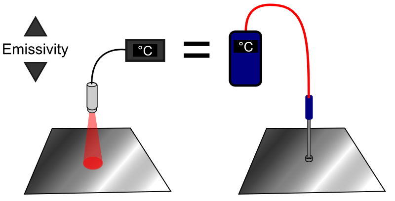
This method involves comparing the measurements from the infrared sensor with a contact thermocouple probe that you trust and know to be accurate.
- Heat the target object (or a sample of the target material) to a steady temperature. Do not attempt this process with the target at room temperature, because in this case you will find that adjusting the emissivity setting has little effect on the measurement. For best results, there should be a significant difference between the target temperature and the ambient temperature.
Ensure there are no hot objects nearby that could cause reflections that interfere with the measurement. Do not perform this process with the target object inside an oven or furnace, near heaters, high intensity lamps etc. The surroundings should have the same temperature as the sensor.
- Measure the target surface temperature with a trusted contact probe. It is important that the probe is in good thermal contact with the surface, and that the measurement is known to be accurate. Note the measurement.
- Remove the contact probe and aim the infrared sensor at the same point on the surface.
OR
Keep the contact probe in position, and aim the infrared sensor very close to it. Be sure the IR sensor cannot “see” the contact probe. If you use this method, be sure the target temperature is the same in both locations. - If the sensor has a Reflected Energy Compensation feature, ensure it is OFF.
- Adjust the emissivity setting on the IR sensor until it measures the same temperature as the contact probe. This is the emissivity setting to use.
Method 3: Compare Measurements with a Known Emissivity
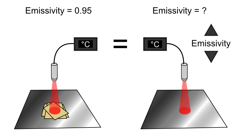
- Paint or coat a measurable area of the surface with a non-reflective coating. Two or three coats of matte black barbecue paint usually works well, and withstands high temperatures too. For lower temperatures, you could try two or three layers of masking tape. Ensure the area you paint is at least twice the size of the sensor’s measured spot – check the optical diagram for your sensor to find the measured spot size for the chosen measurement distance. Leave an uncoated area of the same size next to the painted area.
- Heat the target object (or a sample of the target material) to a steady temperature. The same conditions for step 1 of Method 2 apply.
- Using an emissivity setting of 0.95, measure the painted area. Note the measured temperature.
- Aim the sensor at the uncoated area and adjust the emissivity setting until it measures the same as in step 3. This is the emissivity setting to use.
Making Measurements Easier
If you are measuring a reflective metal surface, you might find the measurement is significantly influenced by reflections. You can make the measurement much more accurate and reliable if you can paint an area to measure. In that case, the emissivity will probably be about 0.95, and reflections will be very much reduced. This will also allow the use of a low-cost general-purpose sensor instead of a more specialised one for metal surfaces.
Consistency is Important
It’s important that the sensor’s emissivity setting matches the target surface, and it’s equally important that the emissivity of the surface stays the same.
If the surface emissivity varies, for example in painting or coating applications where the target surface is sometimes low-emissivity and sometimes high-emissivity, the emissivity setting should be adjusted to the correct value in each case.
If the emissivity only changes rarely, then manual adjustment is often convenient enough. If it happens frequently, then automatic adjustment might be preferred. This could be done by using one of our configurable digital sensors such as the PyroMiniBus, and automatically writing the correct emissivity setting to a Modbus data register via a PLC program or software.
Using Gain and Offset Adjustments with Infrared Temperature Sensors
If a measurement appears inaccurate, it can be tempting to adjust the reading on the indicator or controller using settings like Gain or Offset. This is not recommended – the output of the sensor really should be accurate enough without these adjustments.
If the measurement is not accurate, then the practical factors of the installation and the sensor’s own settings should be investigated first, such as the measured spot size, reflections, and the emissivity setting.
Contact Calex for more advice on setting up our sensors.